Wattstopper Dw 200 Wiring Diagram
Before installing the sensor or working on the load.! All units should be on the same phase.
Wattstopper Elcu200 Wiring Diagram
Refer to the wiring diagram on the next page for the following procedures:

Wattstopper dw 200 wiring diagram. Turn the power off at the circuit breaker. Www.wattstopper.com load line black red neutral ground green ground. When using more sensors than this, multiple power packs are required.
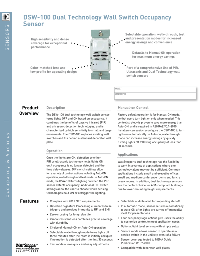
High sensitivity and dense coverage for exceptional performance; Feb 24, · digital lighting management's modular design makes installation a snap, taking just half the time to. • red wire (+24vdc) from power pack to the +24v terminal on the sensor.
• red wire (+24vdc) from power pack to the +24v terminal on the sensor. Taking into consideration bothersome to remove, replace or repair the wiring in an automobile, having an accurate and detailed. To adequately cover the entire space, multiple sensors are positioned to cover a specific zone.
All units should be on the same phase. For best performance, wattstopper recommends Strip gage 1/2 12.7mm visit our website for faqs:
To increase or decrease the lighting level. When using more sensors than this, multiple power packs are required. The dw dual te c h n o logy wall switch sensors combine adva n ced pass i ve.
Coverage pattern wiring diagrams blue primary load secondary load neutral red brown line 2 line 1 black neutral. Watt stopper wiring diagram, dw 200 dual technology dual relay wall switch occupancy sensor, wattstopper legrand pw100w installation instructions, wattstopper commercial lighting control systems legrand, wattstopper cad resource center architectural lighting, sensor adjustment troubleshooting ordering information ci 24, installation instructions bticino, 24 unique. The relays are pro g rammed independently for either auto on or manual on.
Dela mode y additional fea tures ultrasonic sensitivity. Multiple recessed lights diagram occupancy sensor wiring diagram step dimming ballast wiring diagram watt stopper lighting control vacancy sensor wiring diagram recessed electrical light , wattstopper elcu 200 wiring diagram unique elcu 200 wiring so if you want to get this amazing photo about wattstopper elcu Each time the switch is pressed, the load changes state.
(man.) switch and +24vdc terminals as shown in the wiring diagram. Refer to the wiring diagram on the next page for the following procedures: For best performance in single location applications, wattstopper recommends using this sensor in spaces no larger than 18' x 15'.
Connect wires to the dw flying leads as shown in the wiring diagram below that is appropriate to the dw model and electrical supply. It contains two relays for controlling two independent lighting loads or circuits and a variety of features. Wattstopper dlm wiring diagram keyword after analyzing the system lists the list of keywords related and the list of websites with related content, in addition you can see which keywords most interested customers on the this website.
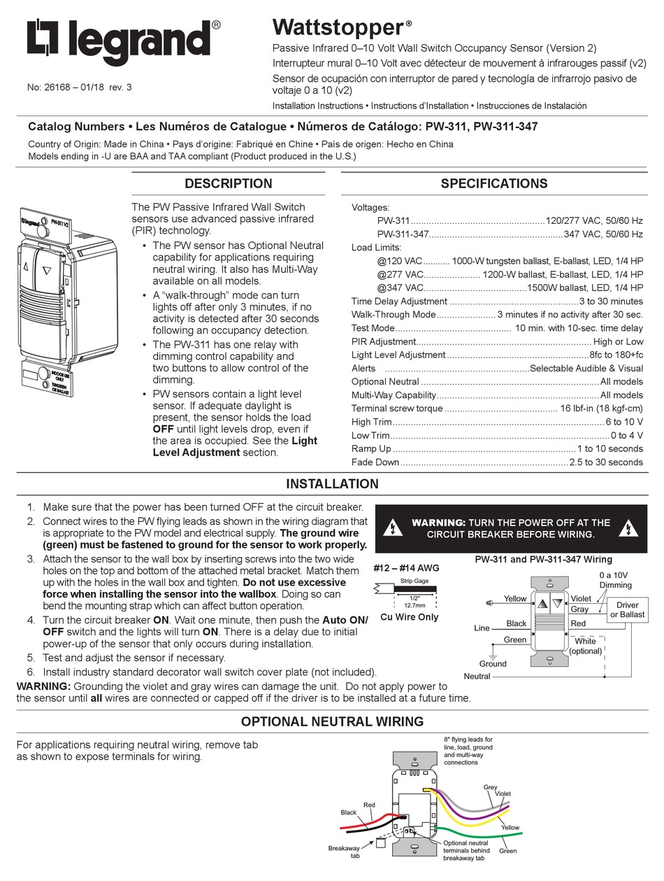
Wattstopper Occupancy Sensor Wiring Diagram Wiring Diagram
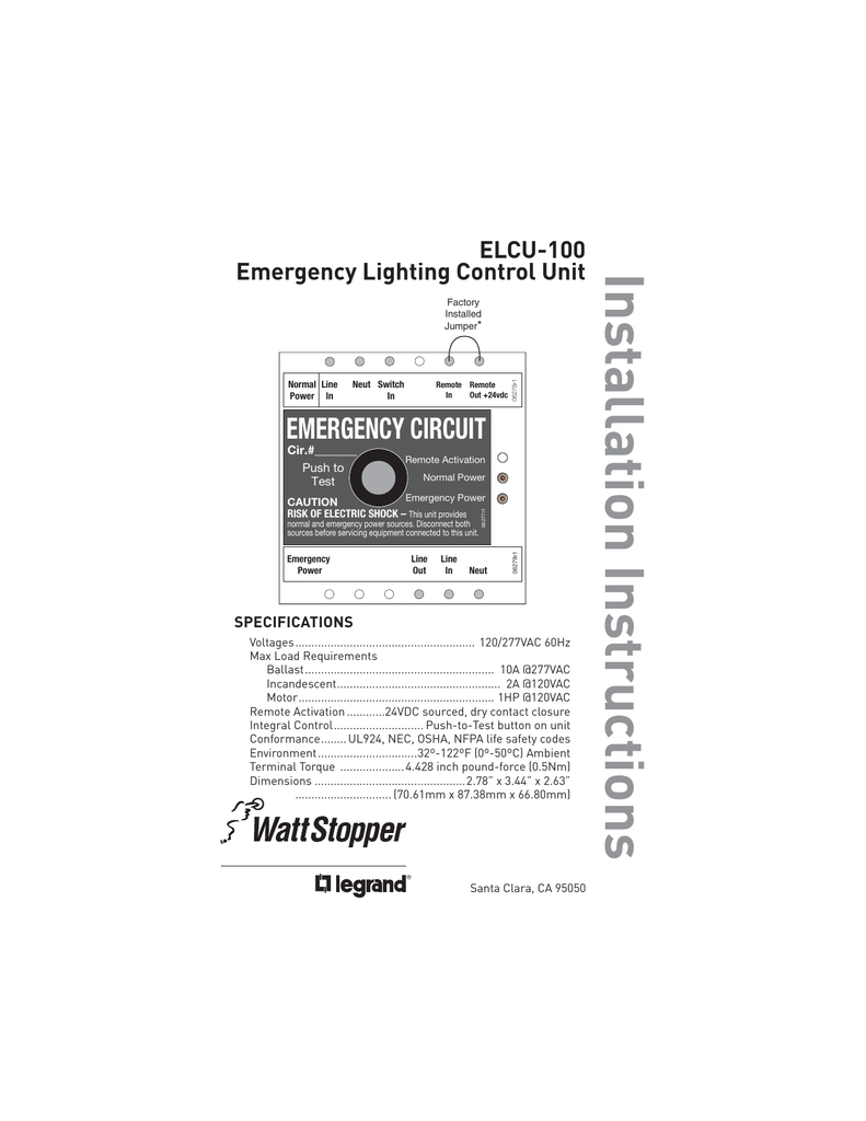
Elcu 200 Wiring Diagram uwelenizone

Elcu 200 Wiring Diagram uwelenizone
19 Unique Wattstopper Wiring Diagrams

Wattstopper Dw 200 Wiring Diagram 19 Unique Wattstopper
[DIAGRAM] Watt Stopper Wiring Diagram FULL Version HD

Wattstopper Dw 200 Wiring Diagram 19 Unique Wattstopper
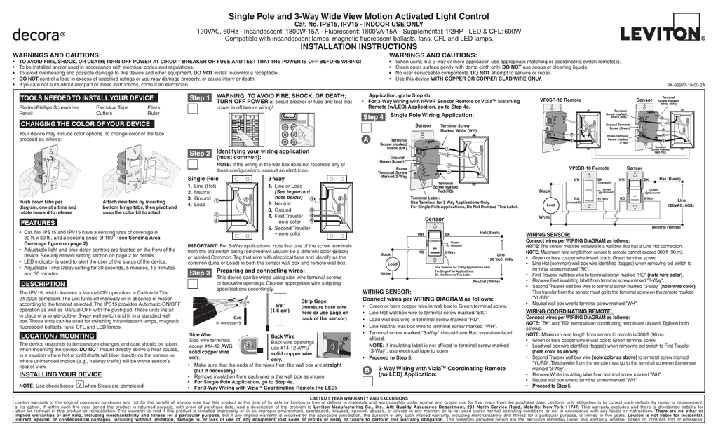
Wattstopper Dw100 Wiring Diagram

Wattstopper Dw 200 Wiring Diagram 19 Unique Wattstopper
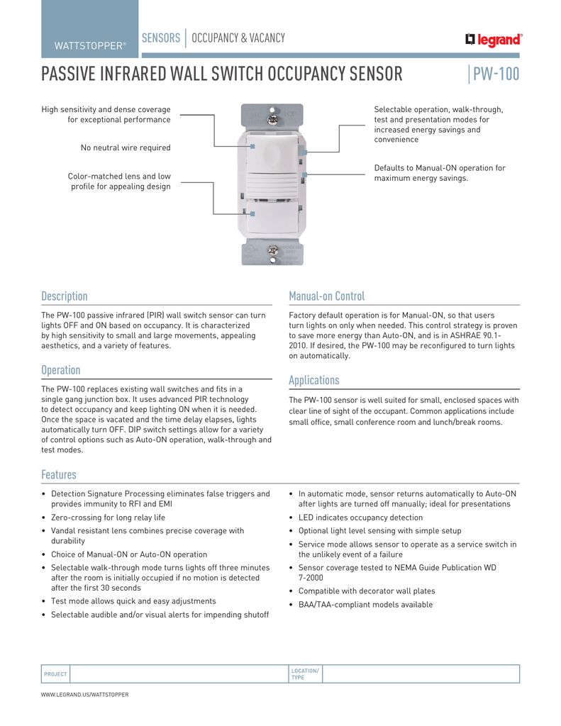
Wattstopper Dw100 Wiring Diagram
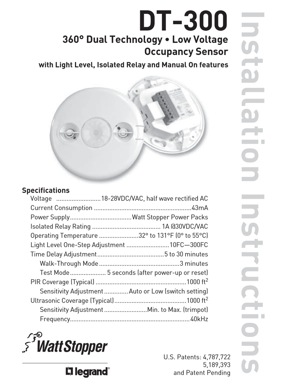
Wattstopper Occupancy Sensor Wiring Diagram Wiring Diagram
WATT STOPPER RS250 PIR CONVERTIBLE OCCUPANCY SENSOR, 120V

Wattstopper Dw 200 Wiring Diagram 19 Unique Wattstopper
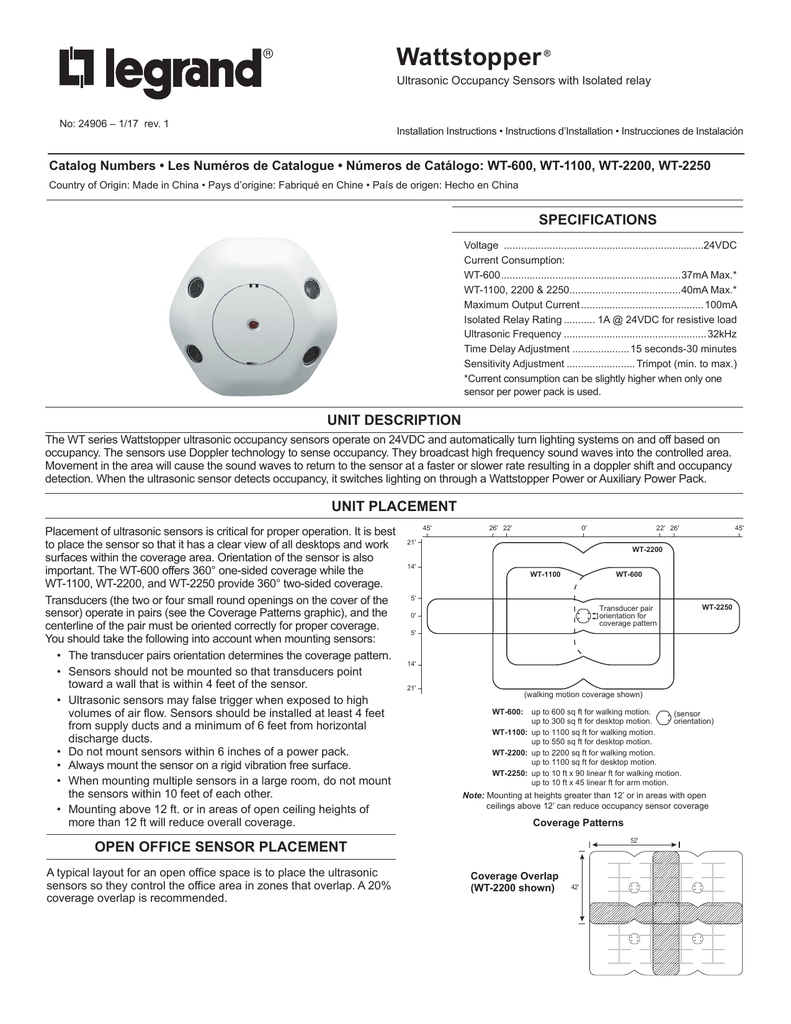
Wattstopper Occupancy Sensor Wiring Diagram Wiring Diagram

Wattstopper dw 200 instructions Canadian Manuals User Guide

Wattstopper Ceiling Mounted Dual Technology Occupancy
